00. First steps into ICs connection and wiring
| Owner | M. G. Sadek |
|---|---|
| Tags |
01. The Objective
In this laboratory tutorial, we will teach you how to identify various ICs and their specification besides tutoring you on how to connect several ICs together using a breadboard.
02. Logic Gates
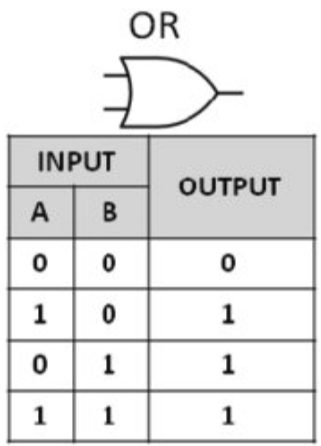
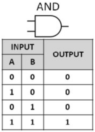
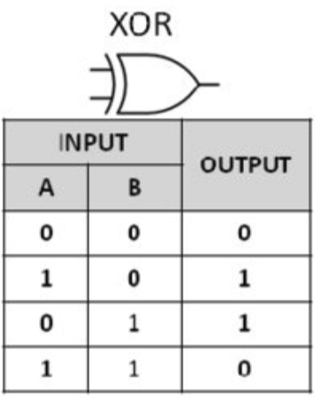
First, we need to introduce the primary three logic gates which we will use to realize Boolean functions later. Note that each gate has its unique truth table.
02.A. Primary Logic Gates Introduction
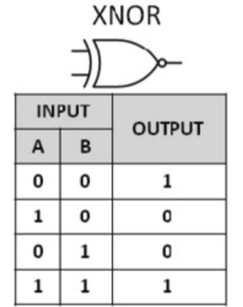
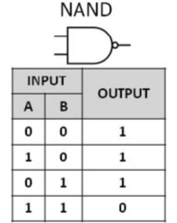
We have four primary gates which can be found in any digital circuit, those gates are:

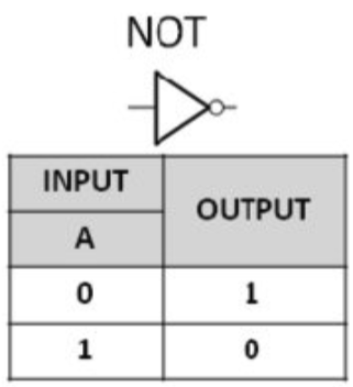
And their inverse gates are:
02.B. The Breadboard
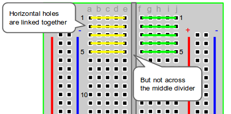
The typical breadboard is laid out in a matrix of .1 inch spaced holes. Most through-hole Integrated Circuit chips or ICs will fit snuggly in this matrix.
The Horizontal and Vertical Layout
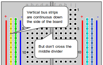
These power rails are also isolated to the right and left sides of the breadboard. If you have to manage two different power supplies or voltages, they can be isolated by keeping them on either side of the board.
02.C. Identifying the ICs Specifications
Those basic logic gates are implemented as small-scale integrated circuits (SSICs) or as part of more complex medium-scale (MSI) or very large-scale (VLSI) integrated circuits. The digital IC gates are classified by their logic operation and the specific logic-circuit family they belong to. As for each logic family, it has its own basic electronic circuit and the following logic families are the most frequently used:
| # | Family name | Full name | Transistor type | Logic 1 Voltage specification | Logic 0 Voltage specification |
| 1 | TTL | Transistor-transistor logic | Bipolar transistors | 5 volts | 0 volts |
| 2 | ECL | Emitter-coupled logic | Bipolar transistors | 5 volts | 0 volts |
| 3 | MOS | Metal-oxide semiconductor | Field effect transistors | 3.3 volts | 0 volts |
| 4 | CMOS | Complementary metal-oxide semiconductor | Complementary metal-oxide semiconductor | 3.3 volts | 0 volts |
02.D. Datasheets
In order to know which ICs to buy and how to connect them you must read its datasheet. You can download any datasheet you need from (https://www.alldatasheet.com/). To guide you let's look at the TC74LCX08F datasheet, in this datasheet you must check its voltage operation value (named: Vcc / Vdd) (i.e. how many volts this IC needs in order to operate properly). In this IC it requires an operating voltage between Vcc = 2.0 ~ 3.3 volts. The second important thing is to know the configuration of the pins:
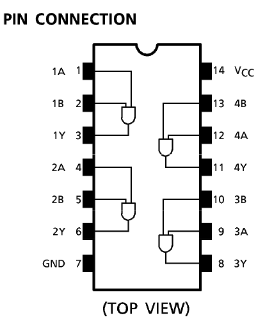
This figure shows that pin 1&2 are the input to the AND gate its output is connected to pin 3.
02.E. Connection Patterns
In order to simulate logic inputs for any digital circuit, you can use push buttons. However, pushbuttons need to have a default value which can be logic 0/1, therefore, there exist two primary patterns which are a pull-down button whose default value is 0 and a pull-up button whose default value is 1. The following figure shows how a pull-down is connected:
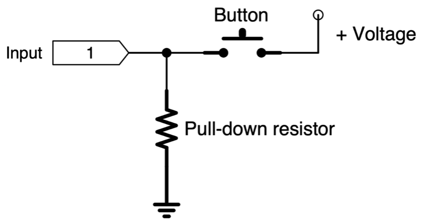
Buttons Truth Table:
| Button pattern | Pressed | Release |
| Pull-down | Input ← Logic 1 | Input ← Logic 0 |
| Pull-up | Input ← Logic 0 | Input ← Logic 1 |
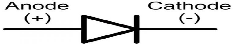
Since the push buttons represent our input signals, then LEDs will hold the output signal (i.e. led on → logic 1. led off → logic 0). Any LED has at least two pins which are called the anode and cathode, to turn on the LED you must connect +Voltage to the anode pin and to turn it off connect 0Voltage (i.e. ground) to the same pin.
03. Classwork
In this tutorial, we are asking you to verify the output of an AND , OR, NOT, XOR gates by connecting two push buttons as inputs to the ICs and an Led as an output on a breadboard, then verify their truth table.