02. VHDL Introduction
| Owner | M. G. Sadek |
|---|---|
| Tags |
01. Introduction
The VHDL (VHSIC (Very High Speed Integrated Circuits) Hardware Description Language) is a hardware description language that is used to describe the behaviour and structure of the digital system. VHDL was originally developed to allow a uniform method for specifying digital systems and it became an IEEE standard in 1987. VHDL can describe a digital system at several different levels- behavioural, data flow, and structural. For example, a binary adder could be described at the behavioural level in terms of its function of adding two binary numbers, without giving any implementation details. The same adder could be described at the data flow level by giving the logic equations for the adder. Finally, the adder could be described at the structural level by specifying the interconnections of the gates which make up the adder.
01.A. VHDL Description of Combinational Circuits
Assume we have this combinational circuit and we need to describe it using VHDL:
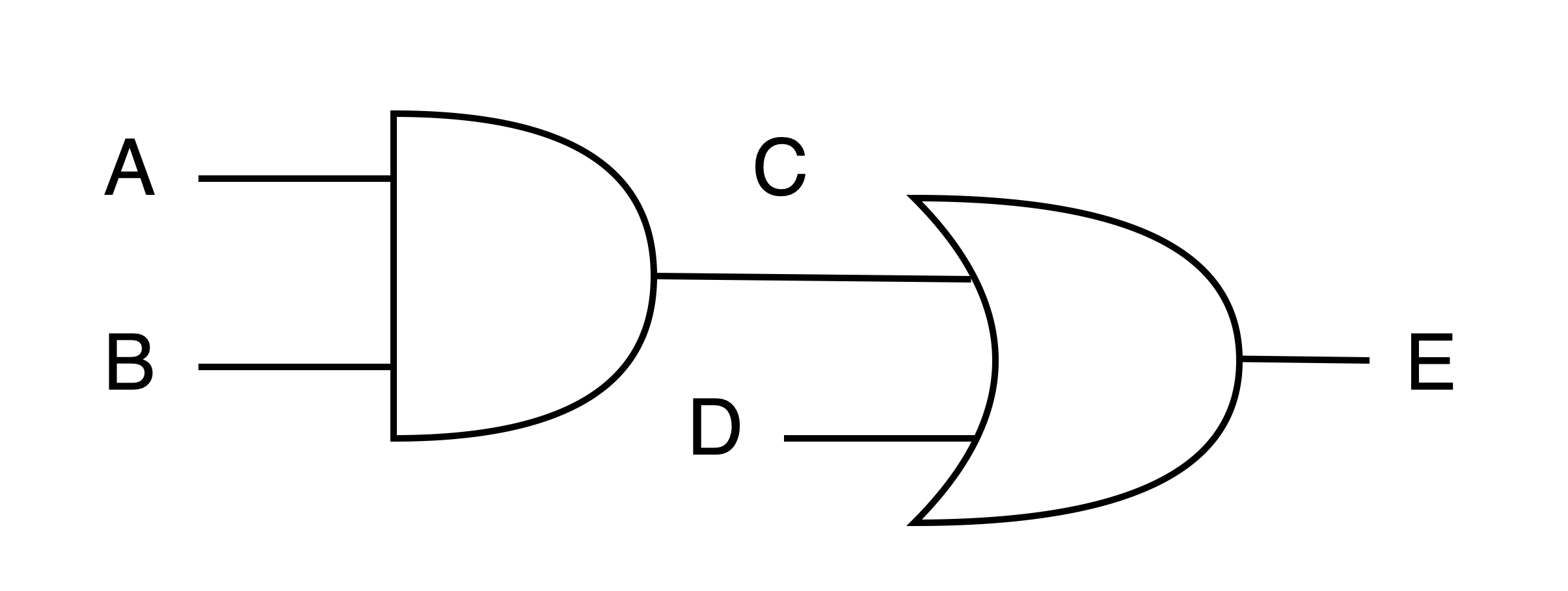
We initially can describe this circuit and ignore the gate delay propagation for now, so we can write:
C <= A and B;
E <= C or D;
This implies that we have two output signals named C and E and three input signals which are A, B, and D. Note that, VHDL programs are not sequential programs which means that those statements shall be executed in parallel which may result in unwanted behaviour.
That is why we need to encounter delay propagation by appending a delay value after each statement.
This means that if A or B changed at time = 0 then C will update its value at time = 5ns followed by E which will be updated at time = 10ns.
C <= A and B after 5ns;
E <= D and C after 5ns;
As a general case, any signal can be described as signal_name <= expression [after delay];.
0.
On another note, we will keep appending VHDL syntax and semantics in later tutorials.02.B. VHDL Code Structure
To write a complete VHDL module, we must declare all of the input and output signals using an entity declaration, and then specify the internal operation of the module using an architecture declaration. Let us consider implementing our previous circuit.
entity two_gates is
	port(A,B,D: in bit; E: out bit);
end two_gates;

architecture gates of two_gates is signal C: bit;
begin
	C <= A and B;
	E <= C or D;
end gates;
The entity declaration gives the name two_gates to the module. The port declaration specifies the inputs and outputs to the module. A, B, and D are input signals of type bit. E is an output signal of the type bit. The architecture is named gates. The signal C is declared within the architecture because it is an internal signal. The two concurrent statements that describe the gates are placed between the keywords begin and end.
02.C. VHDL Code Verification and Validation
After writing your VHDL code, you must check if it's working properly before flashing it on the FPGA. And in order to do so, you can use GHDL and GTKWAVE to check your results.