05. VHDL Modules [2-bit Full Adder]
| Owner | M. G. Sadek |
|---|---|
| Tags |
01 - Objective
In this Lab tutorial, we will re-implement lab-01 to get you familiar with the VHDL module development process.
02 - Logic Gates Implementation
First, we need to create a project as mentioned in lab-03 then in the entity we will define three primary inputs which are X , Y, and C_IN besides defining output signals which are C_COUT, SUM. But before we do this we need to include some IEEE packages which are
library IEEE;
use IEEE.STD_LOGIC_1164.ALL;
then we can define our Entity as
entity fulladder is
	port ( X, Y, C_IN: in std_logic;
        C_OUT, SUM: out std_logic);
end fulladder;
Now we need to define the operation
architecture equations of fulladder is
begin
	SUM <= X XOR Y XOR C_IN after 1 ns;
	C_OUT <= (X AND Y) OR (X AND C_IN) OR (Y AND C_IN) after 1 ns;
end equations;
Full VHDL File for 1-bit Full Adder
-- 1-bit FullAdder

library IEEE;
use IEEE.STD_LOGIC_1164.ALL;

-- Entity Definition
entity fulladder is
	port ( X, Y, C_IN: in std_logic;
        C_OUT, SUM: out std_logic);
end fulladder;

-- Full Adder Operation [Data-Flow Arch.]
architecture equations of fulladder is
begin
	SUM <= X XOR Y XOR C_IN after 1 ns;
	C_OUT <= (X AND Y) OR (X AND C_IN) OR (Y AND C_IN) after 1 ns;
end equations;
Next, we need to implement a 4-bit full adder by cascading 4 1-bit fill adders as shown:
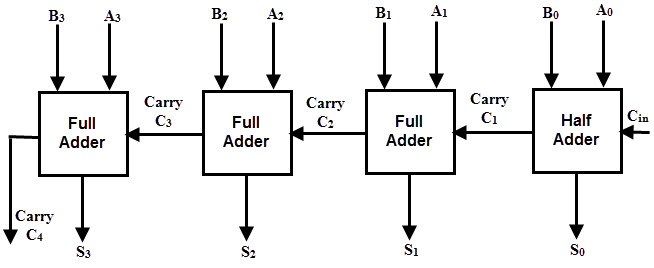
First, we need to define our inputs and outputs:
entity adder4bit is
	port ( A, B: in std_logic_vector(3 downto 0);
			   C_IN: in std_logic;
				 S : out std_logic_vector(3 downto 0);
         C_OUT: out std_logic);
end adder4bit
then we need to include our fulladder into the design but this must be mentioned inside the architecture
architecture structure of adder4bit is

component fulladder
		port ( X, Y, C_IN: in std_logic;
        C_OUT, SUM: out std_logic);
end component;

signal C : std_logic_vector (3 downto 1);
begin
	FA0: fulladder port map (A(0), B(0), C_IN, C(1), S(0));
	FA1: fulladder port map (A(1), B(1), C(1), C(2), S(1));
	FA2: fulladder port map (A(2), B(2), C(2), C(3), S(2));
	FA3: fulladder port map (A(3), B(3), C(3), C_OUT, S(3));
end structure
You can notice that we have mapped the internal fulladder output to the next adder using port map.
Full VHDL File for 4-bit Full Adder:
-- 4-bit FullAdder using Structural Architecture

entity adder4bit is
	port ( A, B: in std_logic_vector(3 downto 0);
			   C_IN: in std_logic;
				 S : out std_logic_vector(3 downto 0);
         C_OUT: out std_logic);
end adder4bit

-- 4-bit FullAdder operation [Structural Arch.]

architecture structure of adder4bit is

component fulladder
		port ( X, Y, C_IN: in std_logic;
        C_OUT, SUM: out std_logic);
end component;

signal C : std_logic_vector (3 downto 1);
begin
	FA0: fulladder port map (A(0), B(0), C_IN, C(1), S(0));
	FA1: fulladder port map (A(1), B(1), C(1), C(2), S(1));
	FA2: fulladder port map (A(2), B(2), C(2), C(3), S(2));
	FA3: fulladder port map (A(3), B(3), C(3), C_OUT, S(3));
end structure
03 - Simulation Process
03.1 - Full Adder
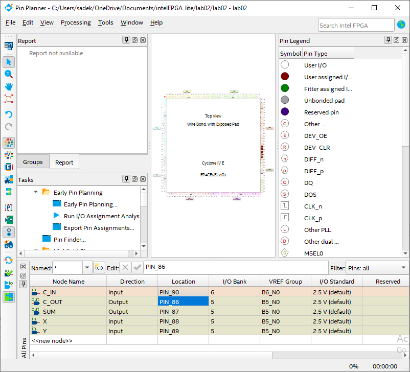
03.1.1 - Pin Assignment
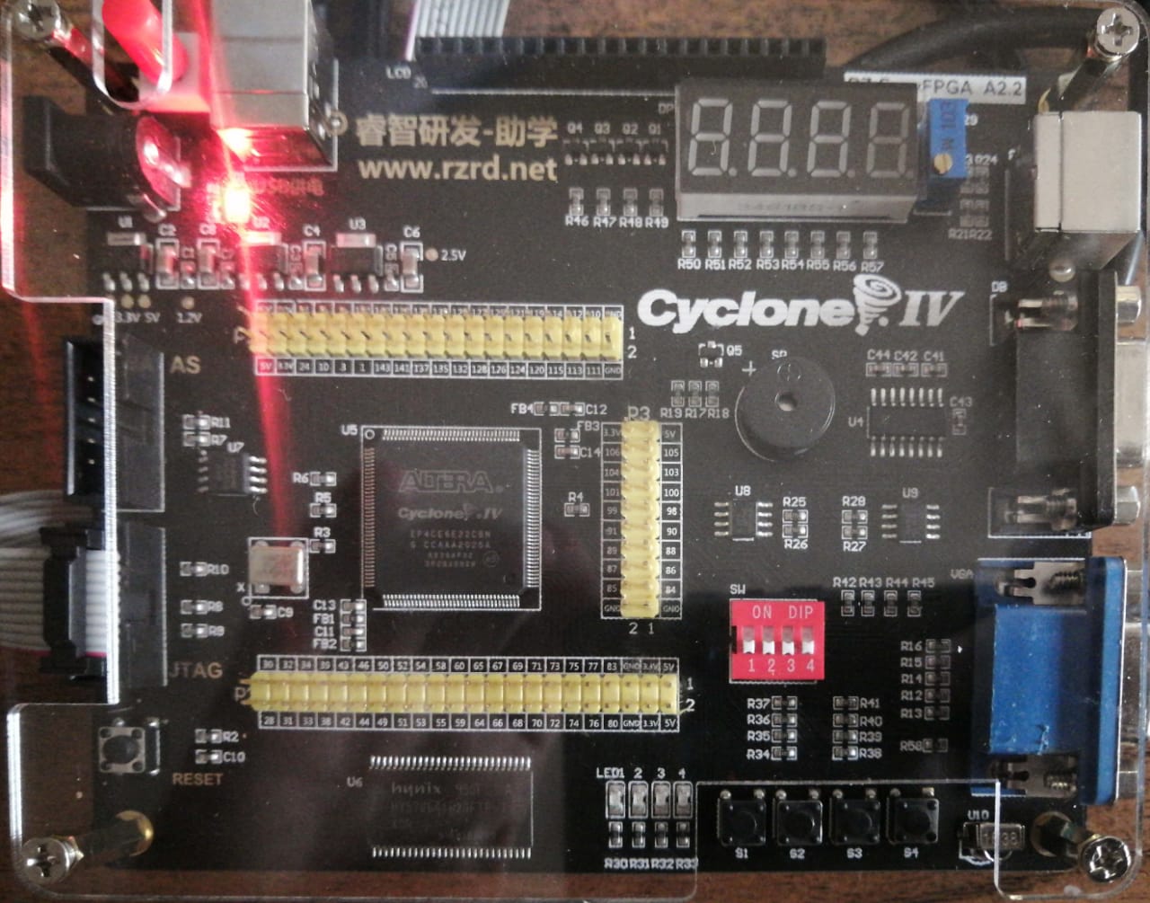
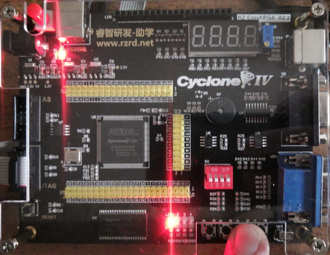
04 - Flashing Process
- The FPGA Kit used has active-LOW push buttons and active-LOW LEDs
- Therefore, we modify our VHDL script into following script, in order to overcome LEDs active LOW and push buttons pull-up resistors design:
library IEEE;
use IEEE.STD_LOGIC_1164.ALL;
use IEEE.STD_LOGIC_ARITH.ALL;
use IEEE.STD_LOGIC_UNSIGNED.ALL;

entity lab02 is
	port ( X, Y, C_IN: in bit;
        C_OUT, SUM: out bit
	);
end lab02;

architecture equations of lab02 is
begin
	SUM <= NOT (NOT X XOR NOT Y XOR NOT C_IN) after 10 ns;
	C_OUT <= NOT ((NOT X AND NOT Y) OR (NOT X AND NOT C_IN) OR (NOT Y AND NOT C_IN)) after 10 ns;
end equations;
Please follow the same steps found in lab-03 in order to synthesise and flash the FPGA.
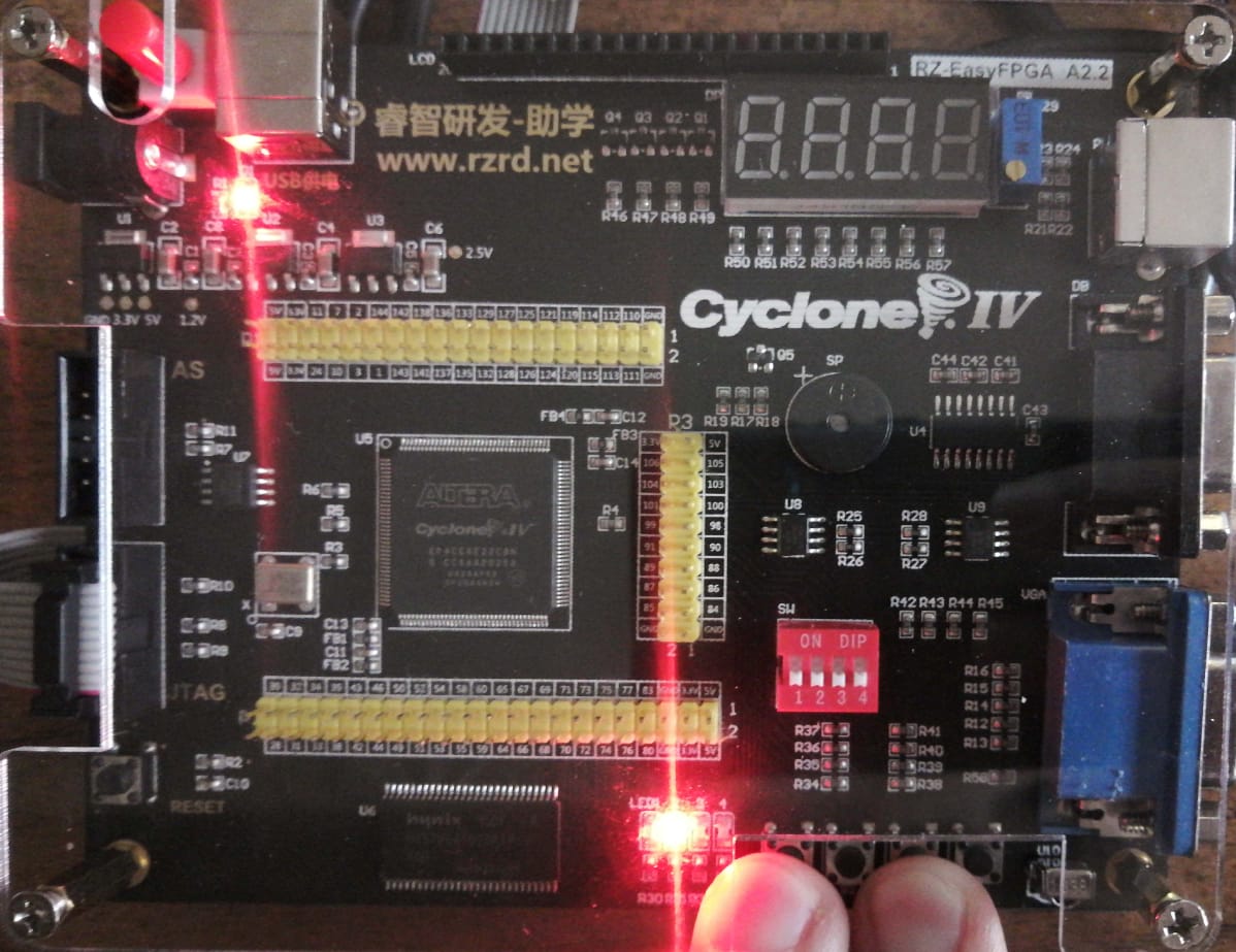
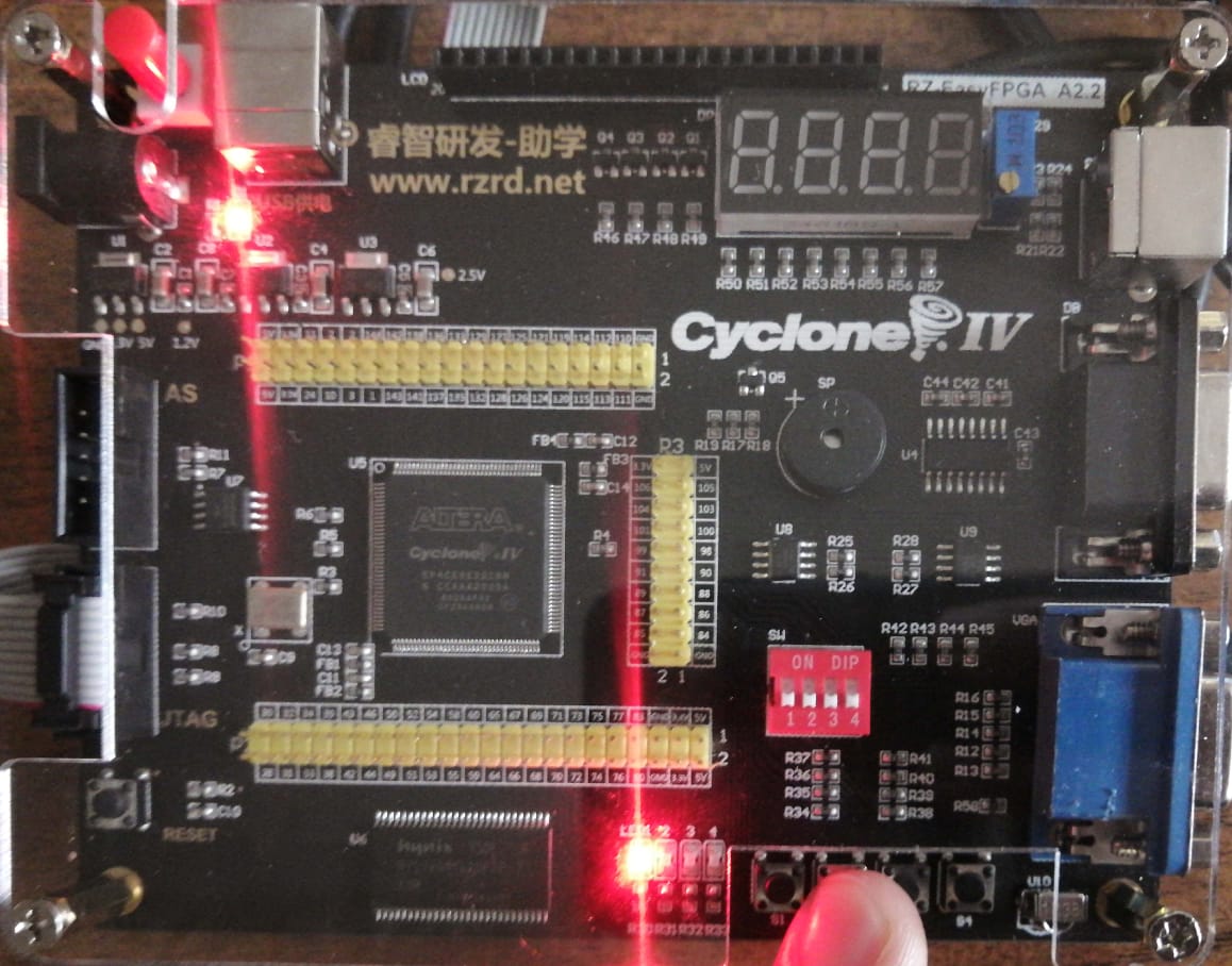
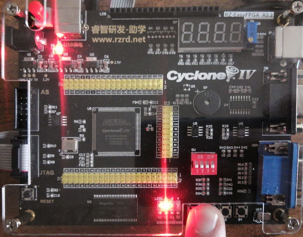
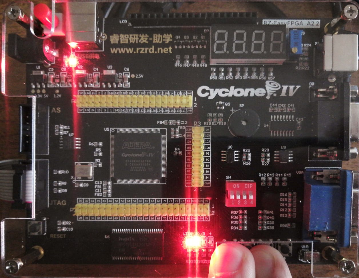
05 - Output Verification
| C_IN | Y | X | SUM | C_OUT |
|---|---|---|---|---|
| 0 | 0 | 0 | 0 | 0 |
| 0 | 0 | 1 | 1 | 0 |
| 0 | 1 | 0 | 1 | 0 |
| 0 | 1 | 1 | 0 | 1 |
| 1 | 0 | 0 | 1 | 0 |
| 1 | 0 | 1 | 0 | 1 |
| 1 | 1 | 0 | 0 | 1 |
| 1 | 1 | 1 | 1 | 1 |
| C_IN | Y | X | SUM | C_OUT |
|---|---|---|---|---|
| 0 | 0 | 0 | 0 | 0 |
| C_IN | Y | X | SUM | C_OUT |
|---|---|---|---|---|
| 0 | 1 | 0 | 1 | 0 |

| C_IN | Y | X | SUM | C_OUT |
|---|---|---|---|---|
| 1 | 0 | 0 | 1 | 0 |
| C_IN | Y | X | SUM | C_OUT |
|---|---|---|---|---|
| 1 | 1 | 0 | 0 | 1 |
| C_IN | Y | X | SUM | C_OUT |
|---|---|---|---|---|
| 0 | 0 | 1 | 1 | 0 |
| C_IN | Y | X | SUM | C_OUT |
|---|---|---|---|---|
| 0 | 1 | 1 | 0 | 1 |
| C_IN | Y | X | SUM | C_OUT |
|---|---|---|---|---|
| 0 | 1 | 0 | 1 | 0 |
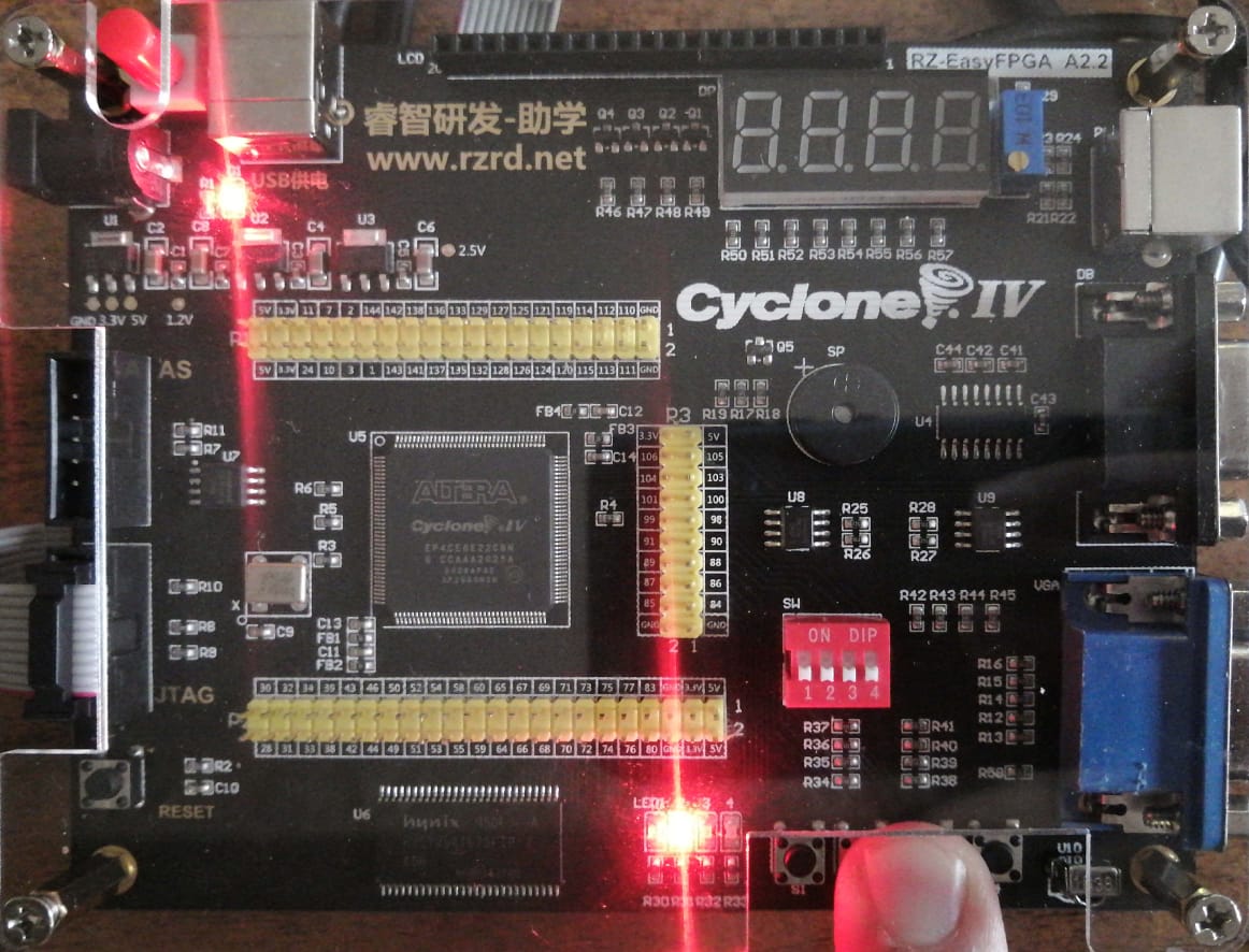
| C_IN | Y | X | SUM | C_OUT |
|---|---|---|---|---|
| 1 | 1 | 1 | 1 | 1 |
06 - Task for next lab
Design a 4-bit Full Adder/Subtractor. Students are required to provide VHDL Scripts for 4bit Full Adder/Subtractor, the testbench. They are also required to provide simulation output, and are required to provide real-time output in the lab.