06. Look-up Tables [1-bit MUX]
| Owner | M. G. Sadek |
|---|---|
| Tags |
01 - Objective
In this tutorial, we will extend your VHDL knowledge to include how to create lookup tables and we are going to use it to synthesize a multiplexer.
02 - Logic Gates Implementation
The simplest multiplexer allows you to select between two inputs using a select line as shown in this figure:
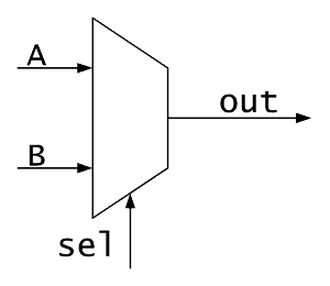
Therefore the out boolean equation can be
which means this is a conditional signal assignment based on the select line, for VHDL conditional signals are written as:
signal_name <= expression_1 when condition_1
               else expression_2 when condition_2
               [else expression_N];
Therefore, let us create a 4 line input multiplexer. First, we need to include our standard libraries
library ieee;
use ieee.std_logic_1164.all;
Then define our entity ’s inputs and outputs:
entity mux4 is
    port (
        i   : in  std_logic_vector(3 downto 0);
        sel : in  std_logic_vector(1 downto 0);
        q   : out std_logic
    );
end entity;
And finally, describe the behavior
architecture conditional_assignment of mux4 is
begin
    -- Conditional signal assigment expression
    q <= i(0) when sel = "00" else
         i(1) when sel = "01" else
         i(2) when sel = "10" else
         i(3); --  sel = "11"
end architecture;
Note you can replace the traditional assignment with select assignment
architecture conditional_assignment of mux4 is
begin
    -- Selected signal assignment expression
    with sel select
        q <= i(0) when "00",
             i(1) when "01",
             i(2) when "10",
             i(3) when others;
end architecture;
03 - Simulation Process
04 - Flashing Process
Please follow the same steps found in lab-03 in order to synthesise and flash the FPGA.